Output
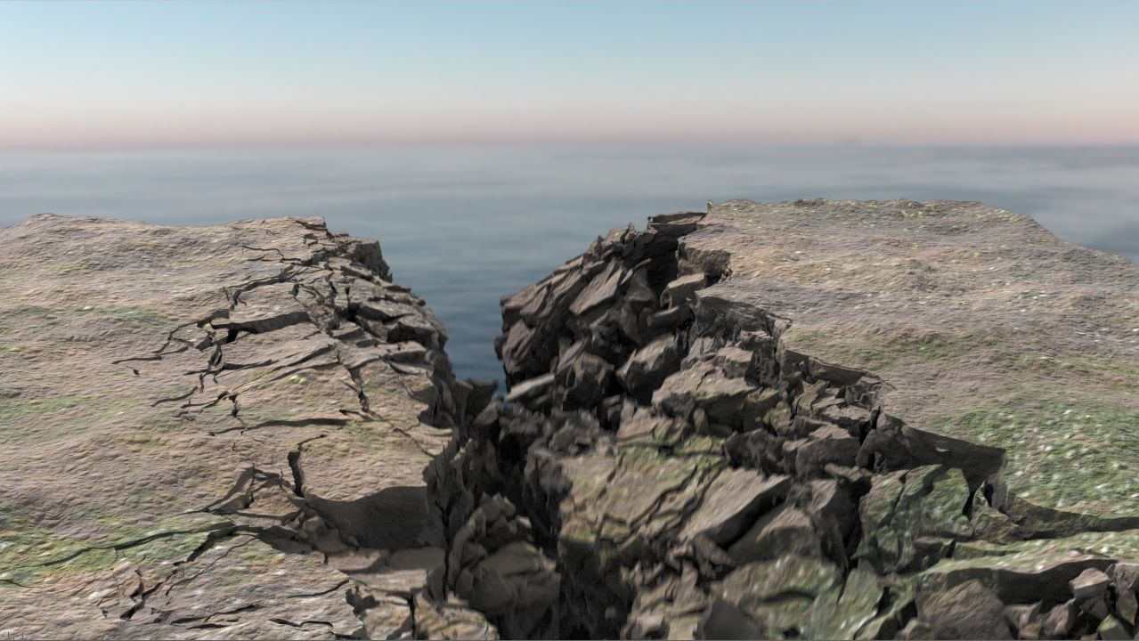
A system for destruction that does not rely on traditional voronoi fracturing and/or clustering of traditional voronoi shapes to produce more organic, realistic shapes.
Create surface and make initial area cuts
1) Initial setup consists of creating the base geometry with an extruded grid and mountain sop.
2) Establish collision walls and inner destruction area by drawing 3 curves on top of the geometry. Extrude the curves to create cutting surfaces.
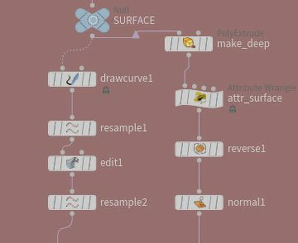
3) Create a surface attribute that will survive the fracture, and record the original normal to use later
2) Establish collision walls and inner destruction area by drawing 3 curves on top of the geometry. Extrude the curves to create cutting surfaces.
3) Create a surface attribute that will survive the fracture, and record the original normal to use later
Create middle area boolean cuts
1) Separate out the middle piece using split, then select the middle cutter, and delete non selected to isolate. Move the curve down to center and use it as as source of points, with a scatter. In this case we used 14 points
2) Use attributerandomize , to randomize the normal use to orient the new cutting planes. Attr name is N for normal. distribution is "inside a sphere". Increase the scale of the normal in Display settings
3) Use a grid in the YZ plane, copy to points, uncheck copy point attributes, because we do not want the normals
4) Use a wrangle to force the Normals in the correct up direction
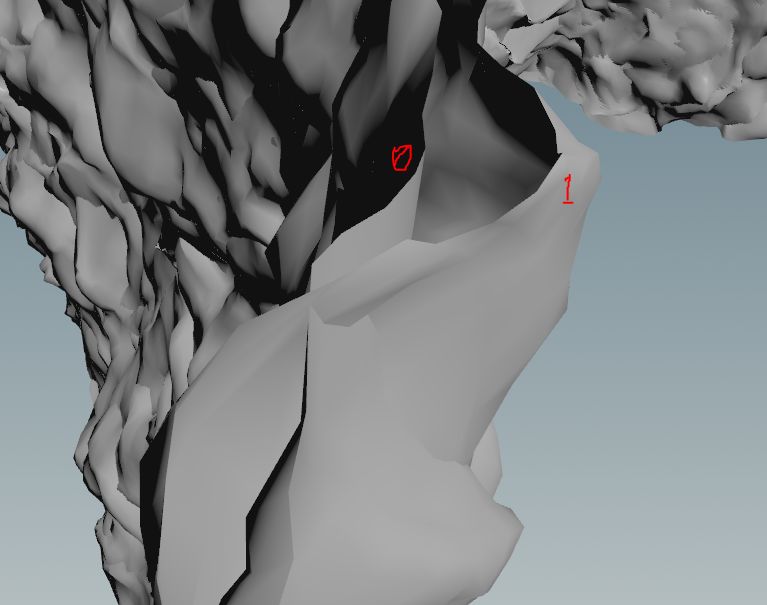
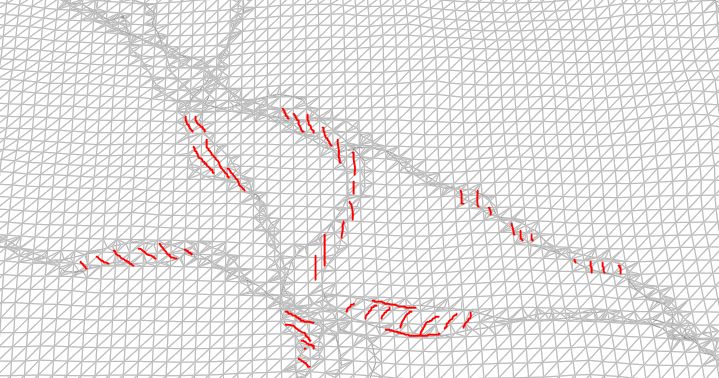
5) Jitter the planes using noise in an Attribute VOP, also use Connectivity to create a class attribute that sets one plane to “1” and the other to “0”, which will be used to offset them inside the Attribute VOP , creating an extra cut between the main chucks. This will serveas the groat or debris between the larger pieces.
6) Cache the pieces
Split off the chucks into separate streams
1) First determine the size using a For Each, Measure Sop, and attribute promote which creates and sums the volume for each piece and promotes it to a Detail Attribute. After, it needs to be demoted back to a Primitve Attribute so it can survive the packing in the
Assemble Sop.
2) The split node reads the volume and used the following expression to separate the small and large pieces: @volume>`chs("threshold")`
3) Larger pieces are processed with another Foreach in a similar way as before but with some important differences:
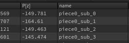
a) The subdivided pieces are renamed based on the old name so they can be fractured further but still held together as a chuck to be broken apart later. The
vex code required: string oldname = point(1,"name",0); (grabs the point name attribute from input 2(1) of the 1st (0th) primitive @name =
sprintf("%s_sub_%s", oldname,i@class);
b) Constraint Network is created and grouped
c) Primitive Group: group_chunks is created
d) Chunks and Constraints are spit off.
4) Groat pieces are split into small and medium, optimized and then merged with the chunks.
5) Outer collision walls are brought in and fractured with Voronoi to produce convex collision hulls.
6) Central cutter is brought together with the main chucks via a Ray Sop to measure the distance of the pieces from the center so they can be activate based on that distance x time, using the point intersection distance
7) Wrangler sets the per piece start_frame according to this: @start_frame = ch(“frame_scale”) * @dist + frame_offset, and also sets a parameter which allows the pieces to be activated: activate i@can_activate =1;
8) Proxy pieces are generated by unpacking the pieces and poly reducing them through a foreach, while using the surface attribute we created before to ensure we don’t lose surface pieces. Also remove pieces that are too small.
9) Simulate using proxy pieces and the delete (with clean sop) everything except the points with the following attributes: Position with 2 intrinsic attributes: 3x3 Matrix (transform) , and Pivot, along with point attributes: velocity (v) and angular velocity (w) (*^pivot, ^transform 6w ^v ^name)
10) Copy the attributes from the proxy pieces to the cached hirez pieces which have the original textures.
Rendering and Texturing
Mantra was used for this project. An interesting technique was used to transfer not just the color and normal attributes from the original surface to the fractured pieces, but also a texture map. This was achieved using the attributefrommap node on the original surface, which takes the texturemap and converts it to Cd.Also storing of the original Normal was very important to prevent the pre fractures from showing before activation.
