Houdini 16, Renderman and Vex Snippets were used to create this forced perspective scene. The system reads an image map, calculates the brightness of each pixel and assigns a larger scale (pscale) to darker ones. The particles are then randomly transformed in z and the scale is corrected for based on the distance to the camera. Geometry is then copied to the points and scaled accordingly. Thanks to Entagma.com for the base set-up. I expanded their system to use a motion picture instead of a static image.
Inspiration
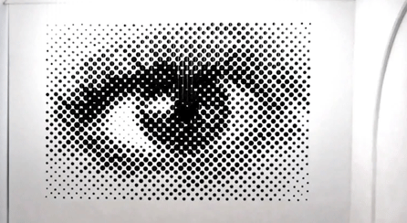
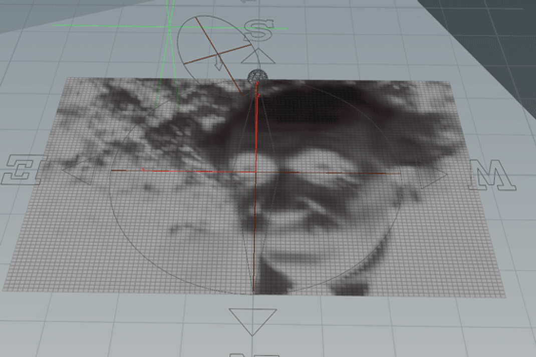
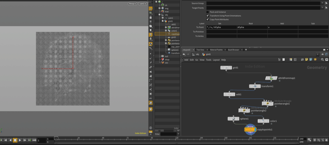
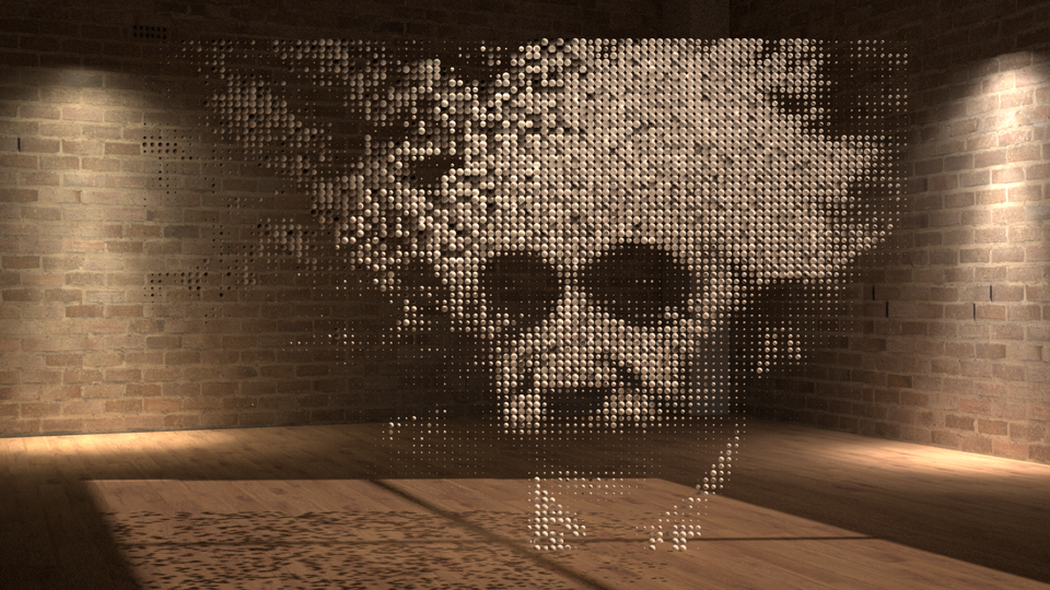
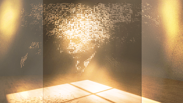
Forced Perspective of Greyscale Image setup
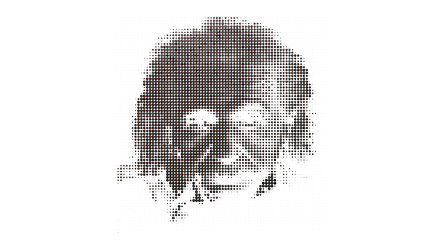
Figure 1
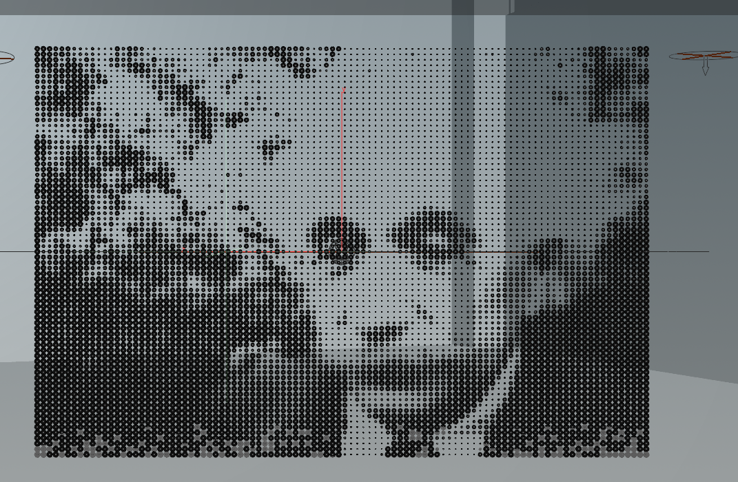
The process starts with adding a simple grid with some resolution (in this case 75 x 100) and attaching an atribfrommap node. The attributefrommap node reads the color and brightness of the underlying image. The add SOP is then used to create points, which inherit the Cd (color) and P (position) attributes. After rotating the grid 90 degrees it appears as in figure 1 above.
The next step is to create two controls that allow the image to be scaled in a procedural way. This is achieved with some very simple vex code inside the powerful point wrangle as follows:
The first snippet creates a float slider to control the resolution of the grid.
int resx = ch("Resolution_X");
The second snippet creates a float slider to control the overall size of the grid (dimensions).
float sizex = ch("Size_X");
Both are linked with a relative reference to the grid node, so you can make changes directly inside the point wrangle.
To get the maximum radius of the points/spheres the size of the grid is divided by the resolution. In this case it is 1.5 / 100 so the max radius is 0.015
Therefore:
float scale = sizex / float(resx);
Since the system uses the individual point color/brightness to determine the individual scale of the dots, the color needs to be read first, which is then converted to a brightness value by averaging the individual components of the color vector:
vector col = v@Cd; and
float grey = (col.r + col.g + col.b) / 3.0;
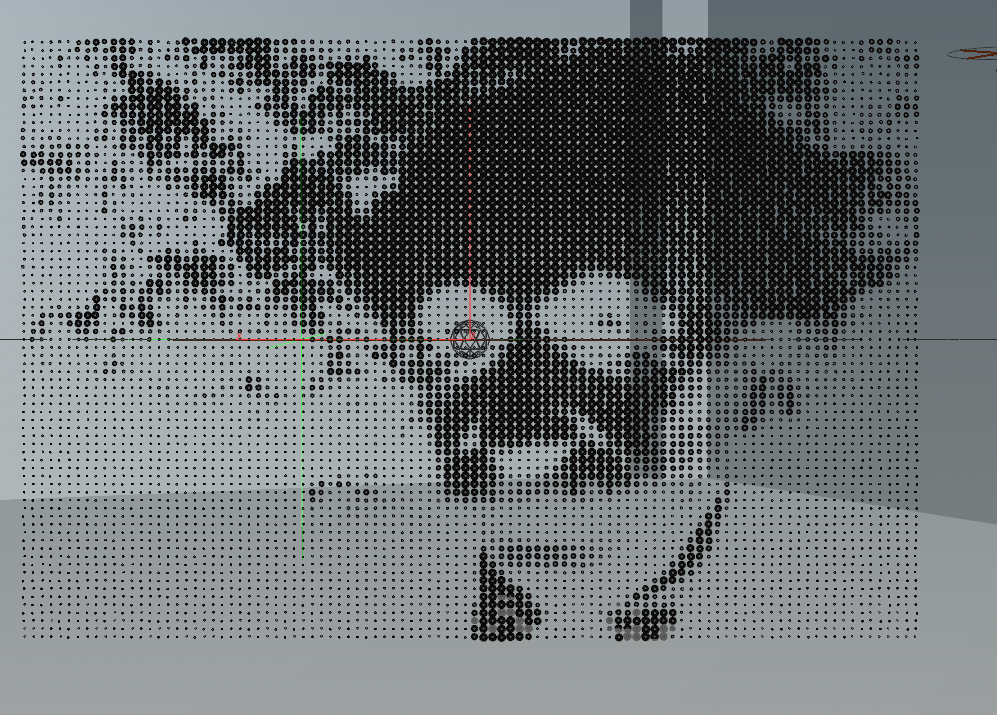
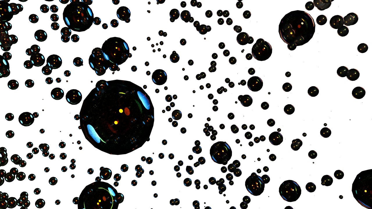
This produces larger values for brighter points, which when subtracted from 1 produce a smaller scale for brighter points, which are used to create a new attribute called pscale. This is important because if you look at a newsprint image it is the scale of dots that make up the image.
f@pscale = (1.0 - grey) * scale * 0.5;
The next step is to create two controls that allow the image to be scaled in a procedural way. This is achieved with some very simple vex code inside the powerful point wrangle as follows:
The first snippet creates a float slider to control the resolution of the grid.
int resx = ch("Resolution_X");
The second snippet creates a float slider to control the overall size of the grid (dimensions).
float sizex = ch("Size_X");
Both are linked with a relative reference to the grid node, so you can make changes directly inside the point wrangle.
To get the maximum radius of the points/spheres the size of the grid is divided by the resolution. In this case it is 1.5 / 100 so the max radius is 0.015
Therefore:
float scale = sizex / float(resx);
Since the system uses the individual point color/brightness to determine the individual scale of the dots, the color needs to be read first, which is then converted to a brightness value by averaging the individual components of the color vector:
vector col = v@Cd; and
float grey = (col.r + col.g + col.b) / 3.0;
This produces larger values for brighter points, which when subtracted from 1 produce a smaller scale for brighter points, which are used to create a new attribute called pscale. This is important because if you look at a newsprint image it is the scale of dots that make up the image.
f@pscale = (1.0 - grey) * scale * 0.5;
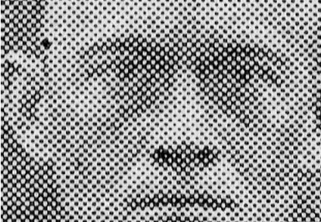
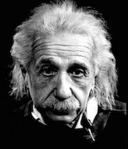
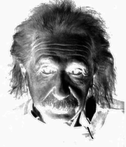
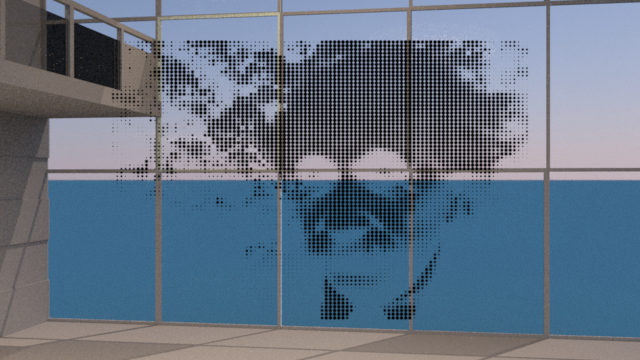
LEARNING POINT: When I first started testing this system I used a black and white Einstein image that had bright values for his head, face and hair on a black background, so the effect was smaller spheres for the bright areas and larger spheres for black background. This created a hollowed out effect for the particle cloud which still showed the face, but it was opposite of the way I wanted it. I fixed it the hard way by inverting the image in photoshop and reading it in again so the density was in the center. Later I did the same for the sequence in Nuke. As I began to understand the code further, I realized I never had to invert the image or the sequence. All I needed to do was alter the code to remove the "1-" grey to be:
f@pscale = grey*scale 0.5
f@pscale = grey*scale 0.5
The image below show the result of changing the script, which produces a negative image, but when the particles are shaded white on a dark background it flips the image back while keeping the density in the inside areas.
Initial Node Network
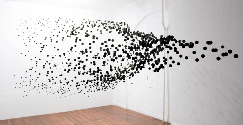
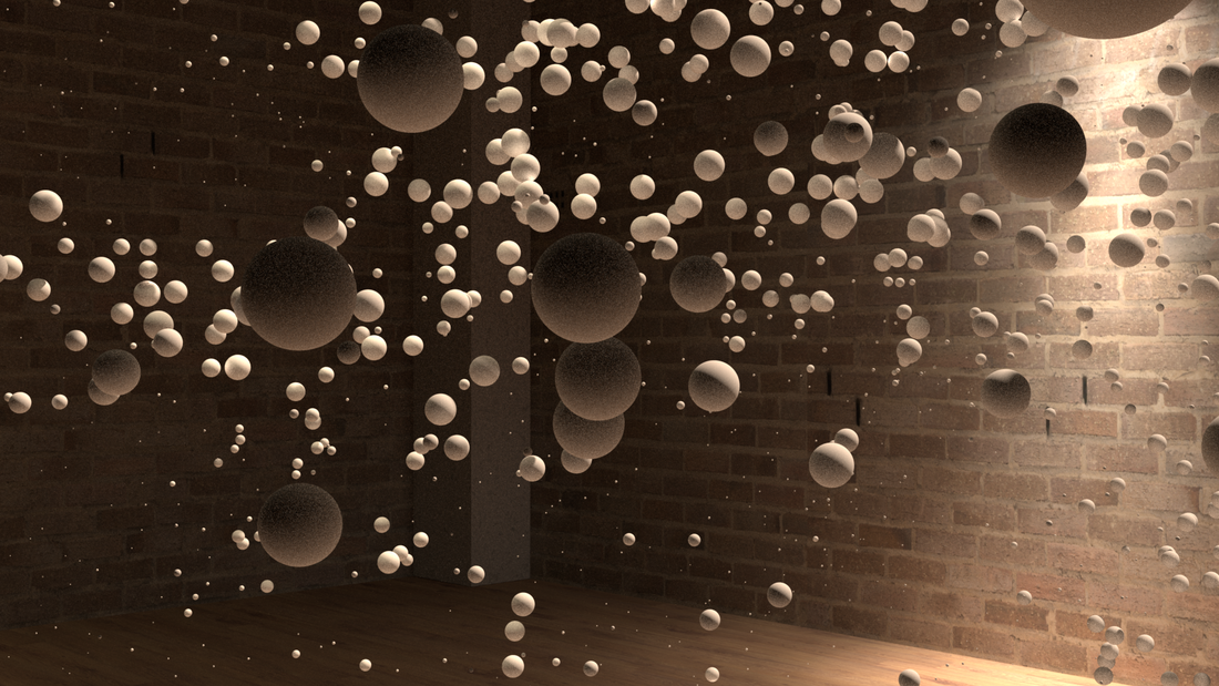
Creating the 3d effect
To create a particle cloud effect, the points need to be transformed randomly in z, and then corrected for the distance to the camera taking into account the change of perspective. This can be achieved be capturing the user defined camera position data from the camera and linking it with a relative vector channel reference input. As a vector quantity, it would be:
vector campos = vch("Cam_Position");
To move the particles in Z (off the face of the plane towards the camera) a distance needs to be defined (in this case called amplitude), and to randomize that distance and have a chaotic looking particle cloud, a random seed input is required:
float amp = chf("Amplitude");
float seed = chf("Seed");
To calculate the current distance of the particles from the camera, their position vector has to be read with a new variable and subtracted from the camera position "campos" from above:
vector pos = v@P
Now we have the inputs needed to calculate the z distance component (zdist):
float zdist = pos.z - campos.z;
Actually moving the particles randomly in z using the seed and amp inputs requires that we define another simple expression called zoffset:
float zoffset = rand(@ptnum + seed) * amp; where "rand" creates a random number from the sum of the current point number (@ptnum) plus the seed multiplied by the user defined amplitude (distance).
correcting for the size and position of the randomly placed particles
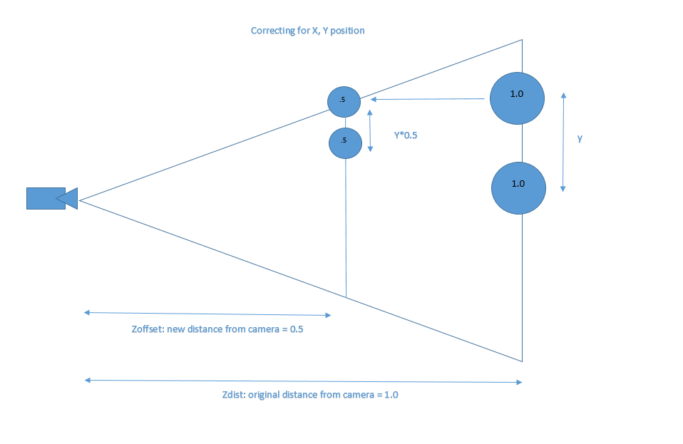
This part was a little tricky to understand at first, but a picture helps to get the concept in general. In the diagram below we will assume the original distance from the camera is 1. The diameter of the sphere is also 1. The sphere is transformed halfway (0.5) to the camera (zoffset), so it will appear exactly two times the original size, so it makes sense that diameter will have to be reduced by a factor of 0.5 (see chart 1). Due to the frustum of the camera, the particles position will need to be offset by the same amount in both X and Y to avoid them moving outside the camera view (see chart 2).
Chart 1 The new distance represents the zoffset
Chart 1 The new distance represents the zoffset
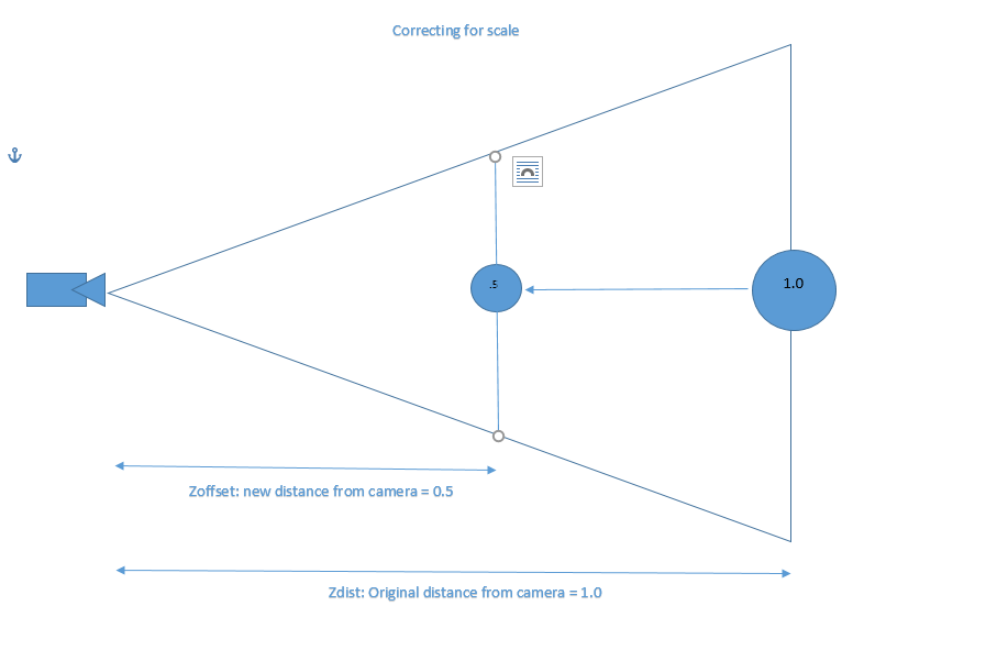
Chart 2 Showing the Y, we can see how the position needs to be offset by the same amount as the zoffset in both X and Y
To calculate the offset along the X/Y axis we know that the closer the random zoffset particle is to the original distance (zdist) the smaller the x/y offset should be. In the chart above you can see that if we move the particle towards the right (closer to the original distance) the correction amount would decrease until there was no correction at all and it would be back at the original location. To calculate this, we need another variable called the xyoffset using a fit expression to take the zoffset which is a value between: "0.0" and the "zdist" and remap it to a value of "1" if zdist = 0 and a value of "0" if zdist = zoffset. In "english" that means if the zdist and zoffset are the same there is no offset (0%), and if the zdist is at the camera (zero distance) then offset would be 100%, there fore:
float xyoffset = fit(zoffset, 0.0, zdist, 1.0, 0.0); for reference the houdini fit expression is defined as:
fit(num, oldmin, oldmax, newmin, newmax)
Finally, there is enough information to calculate the scale and position of a given sphere by:
1) multiplying the original x,y positions by the xyoffset amount
2) subtracting the xyoffset from the original z position
3) Multiplying the pscale by the xyoffset
Therefore:
v@P = set(pos.x * xyoffset, pos.y * xyoffset, pos.z - zoffset);
f@pscale *= xyoffset;
Scene Set up and rendering
Maya:
Initially, the plan was to create the particles in Houdini then export as alembic to Maya. This worked and I tested a few ideas before deciding to stay inside of Houdini for rendering.
Initially, the plan was to create the particles in Houdini then export as alembic to Maya. This worked and I tested a few ideas before deciding to stay inside of Houdini for rendering.
Houdini:
The decision to use Houdini complicated the rendering process somewhat, because it required learning how to set up and use Renderman in Houdini at the same time as learning Renderman in general. The process to set up Renderman for Houdini requires a few steps that must be followed or it will not work:
1) Add Renderman 21 under edit/preferences/rendering/ then check Renderman 21
2) Add the Renderman shelf tool under shelves then select Renderman RIS
3) In the OUT context and add the Renderman RIS ROP
4) Go inside the SHOP context and add RIS Shader Network
5) Go inside the RIS Shader Network and drop down a pxrpathtracer node
6) Go back to the OUT context and click on the RIS ROP add the pxrpathtracer to the integrator field
7) Go back to the RIS Shader Network in the SHOP context and put down a pxrsurface bxdf material
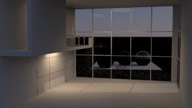
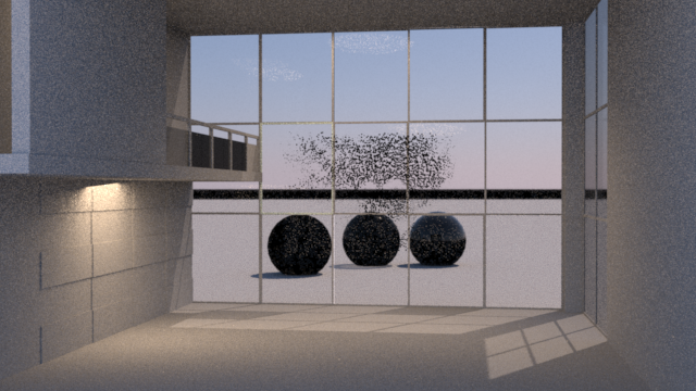
Scene set up:
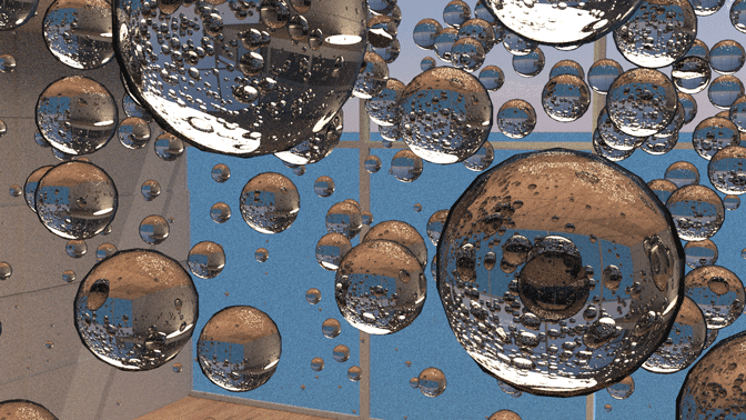
Once Renderman was set up and working, I started testing various ideas for lighting, environments, and particles. Below are some of the early stages of setting up lighting, and interior and exterior environments, as well as numerous tests for particle shaders.
Once Renderman was set up and working, I started testing various ideas for lighting, environments, and particles. Below are some of the early stages of setting up lighting, and interior and exterior environments, as well as numerous tests for particle shaders.
Initial scene: testing interior and exterior lighting, environment lighting

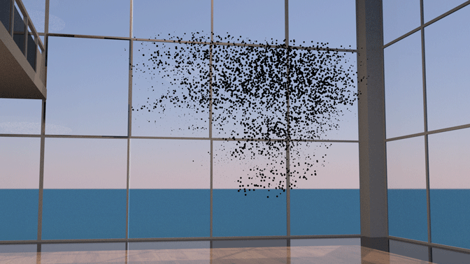
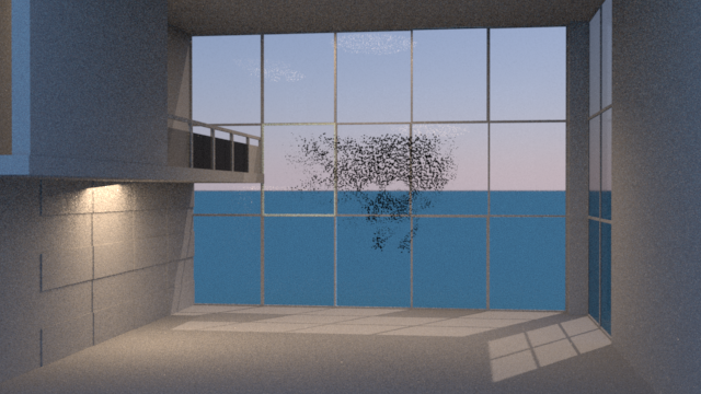
Ocean Front Concept:
Tested multiple scenarios for an ocean front scene but ended up moving away from this idea. Lesson learned here included resolving trace depth issues after getting black reflections in glass and water. A trace depth parameter had to be added for each object under "edit parameter interface" under Rendering. Also learned how to enable and configure depth of field.
Tested multiple scenarios for an ocean front scene but ended up moving away from this idea. Lesson learned here included resolving trace depth issues after getting black reflections in glass and water. A trace depth parameter had to be added for each object under "edit parameter interface" under Rendering. Also learned how to enable and configure depth of field.

Indoor Scene:
After getting feedback, I decided to pursue an indoor scene instead. I kept some of the indoor light but rebuilt the scene with my own geometry. I started by closing off the room of the model and created a single window with a directional light. Next I added a fog shader to the light. The objective was to create a darker ghostly scene. The scene ended up too dark, and after some histogram testing in photoshop I added more lights. The new lights used IES filters to provide more realistic falloff and bulb refraction.
After getting feedback, I decided to pursue an indoor scene instead. I kept some of the indoor light but rebuilt the scene with my own geometry. I started by closing off the room of the model and created a single window with a directional light. Next I added a fog shader to the light. The objective was to create a darker ghostly scene. The scene ended up too dark, and after some histogram testing in photoshop I added more lights. The new lights used IES filters to provide more realistic falloff and bulb refraction.
Textures and rendering
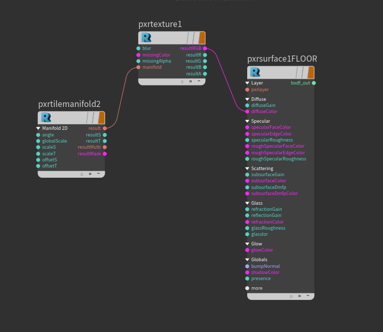
Primarily used Pxrsurface in combination with Pxrtexture pattern node as well as Pxrtilemanifold to apply texture maps. I used three high res 4k textures from cgtextures.com including a wood floor, brick wall and granite post.
Motionblur:
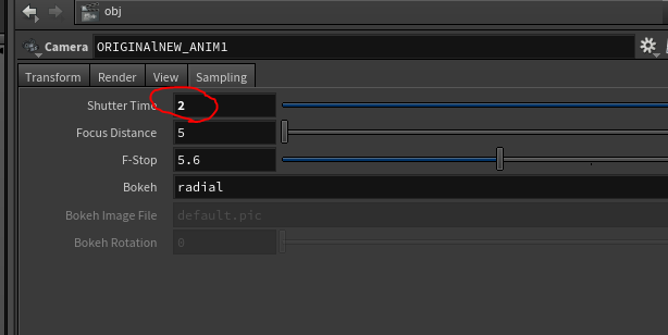
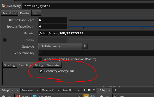
Initially unsuccessful, I was able to get motion blur working after a significant amount of R&D. The issue for my scene was that none of the particles are actually moving although they look like they are, so I had to focus on camera blur. I managed to get the camera blur working by enabling: "Geometry Velocity Blur" on the particle/sphere object, increasing the shutter opening range from 0,1 to -1,1 on the ROP, as well as increasing the shutter time on the camera from 1 to 2. The effect introduced some noise, so I increased motion blur samples including the Geo Time samples and the XfromTime Samples on the ris rop. This fixed the issue with a minimal increase in render time.
Initially unsuccessful, I was able to get motion blur working after a significant amount of R&D. The issue for my scene was that none of the particles are actually moving although they look like they are, so I had to focus on camera blur. I managed to get the camera blur working by enabling: "Geometry Velocity Blur" on the particle/sphere object, increasing the shutter opening range from 0,1 to -1,1 on the ROP, as well as increasing the shutter time on the camera from 1 to 2. The effect introduced some noise, so I increased motion blur samples including the Geo Time samples and the XfromTime Samples on the ris rop. This fixed the issue with a minimal increase in render time.

SUMMARY AND CONCLUSIONS
Overall, I am pleased with results, and especially the knowledge gained. Even though I just scratched the surface of what Renderman can do, I was able to experience some of the powerful features. I was particularly impressed with the denoiser technology and I liked the familiar the user interface. The speed of the renders was also impressive, allowing me to fully render several high quality iterations within the limited time and on local machines. I am looking forward to learning more and testing it some volumes.
Self critique:
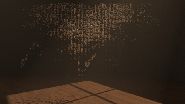
Even though the shot is 350 frames it seems to leave the viewer expecting something at the end. When viewed now I think there should be some kind of image or message in the particles the very end instead of fading to black before the final message of "Rest in Peace Science" in Latin. If I were to do it again I would focus more on rigging a system where I could get the message across as part of the particle system, at least with some kind of trick with lighting or shadows.
Future:
I did not end up getting displacement to work, so I will definitely need to investigate that. I would also like to develop my skills in texture mapping.
Self critique:
Even though the shot is 350 frames it seems to leave the viewer expecting something at the end. When viewed now I think there should be some kind of image or message in the particles the very end instead of fading to black before the final message of "Rest in Peace Science" in Latin. If I were to do it again I would focus more on rigging a system where I could get the message across as part of the particle system, at least with some kind of trick with lighting or shadows.
Future:
I did not end up getting displacement to work, so I will definitely need to investigate that. I would also like to develop my skills in texture mapping.